Reisinger.Tech
I vibe-coded my bookshelf speakers into bluetooth speakers
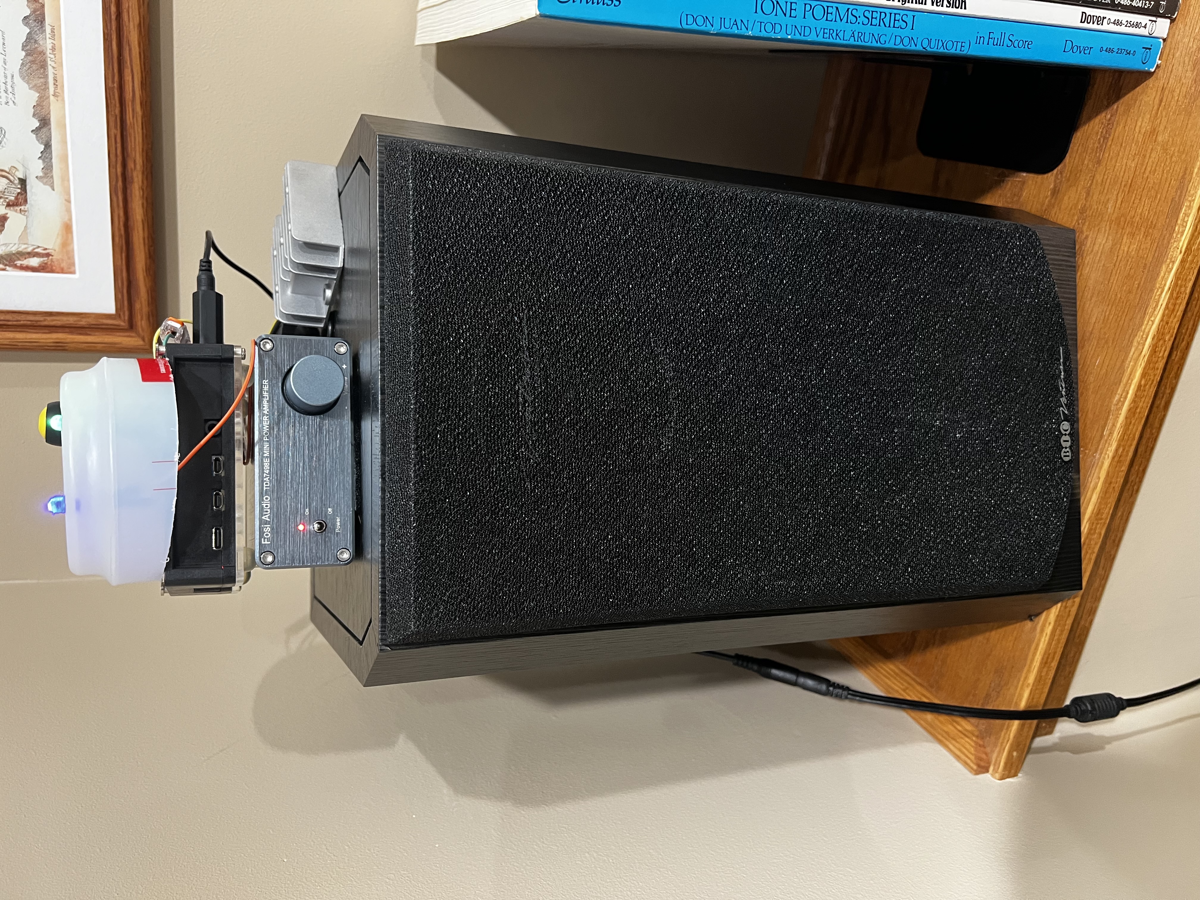
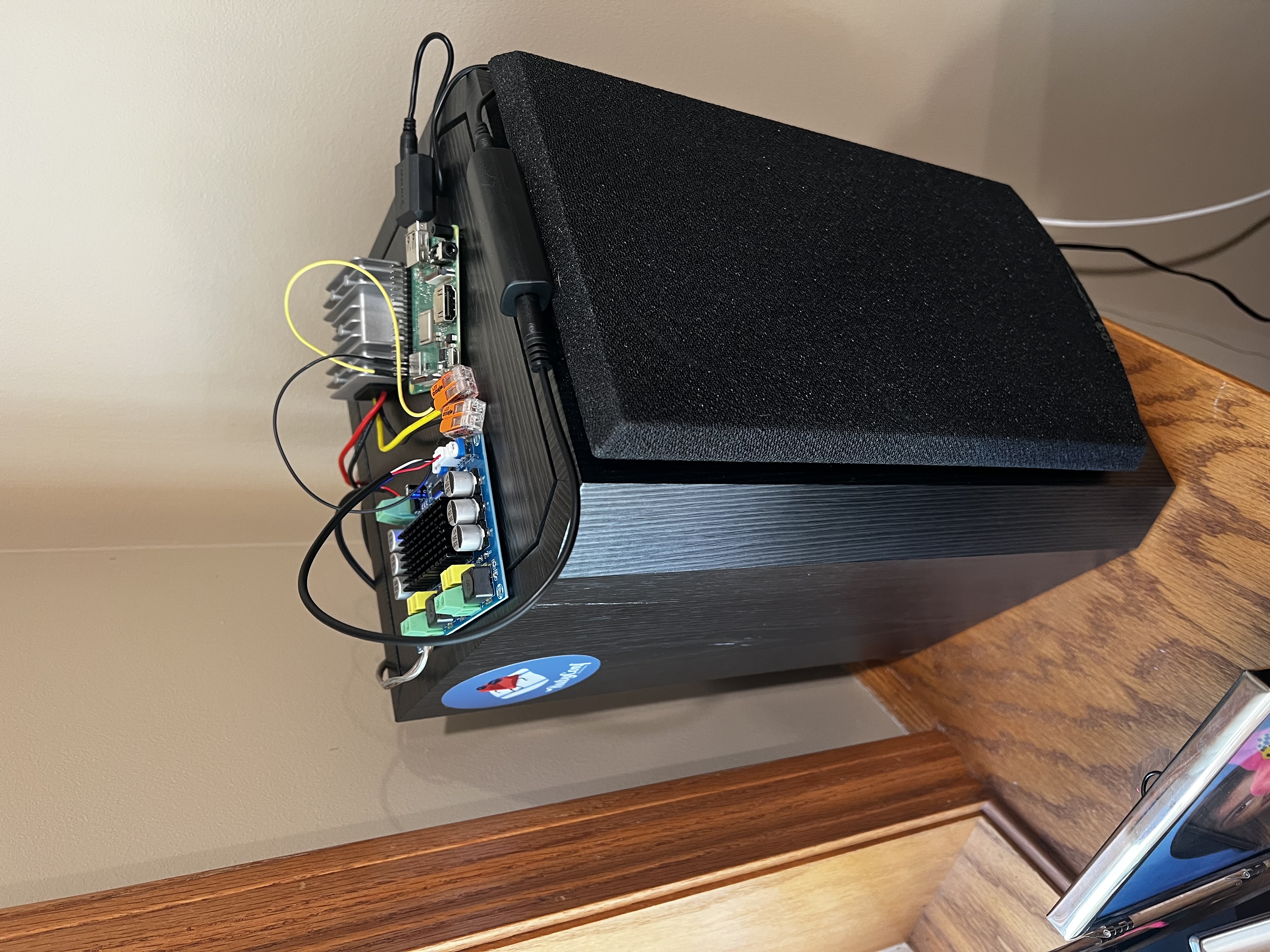
I had a pair of BIC dv62si bookshelf speakers in my office that were doing nothing, connected to nothing, collecting dust. I also had a drawer full of Raspberry Pis. The obvious move was to turn them into a wireless stereo pair that I could stream to from my phone, so I did that — with Claude doing most of the heavy architectural lifting while I did the wiring and debugging.
- Approach
- Architecture
- Parts
- Power
- Audio Stack
- Pairing Button and LEDs
- Right Speaker
- Web Interface
- Conclusion
Approach
Before touching any hardware, I used Claude to work through three possible architectures. The first used two Pis connected over WiFi with Snapcast handling audio synchronization. The second used a Pi and an ESP32 microcontroller communicating over UDP, which would have required writing custom firmware in C. The third relayed audio from the Pi to an ESP32 over a second Bluetooth connection, an interesting topology that would have been hard to keep in sync. I went with the first approach. Snapcast was designed exactly for this problem — synchronized multi-room audio — and it meant no custom firmware, standard packages, and SSH access to both devices for debugging.
Architecture
The left speaker (Pi 4B) is the master. Your phone connects to it over Bluetooth and streams audio via the A2DP profile. The Pi receives the audio through BlueZ and PipeWire and writes it into a named pipe on disk. A Snapcast server reads from that pipe, adds precise timestamps to the audio stream, and broadcasts it over WiFi.
The right speaker (Pi 3 A+) runs a Snapcast client that connects to the left speaker over the local network, receives the timestamped stream, and plays it back through its own USB audio adapter and amplifier. Snapcast’s synchronization keeps both speakers within about a millisecond of each other — close enough that holding them side by side produces a single clean sound rather than an echo.
The two Pis only need to be on the same WiFi network. There is no wired connection between them. The right speaker finds the left at boot using mDNS — it looks up left-speaker.local, connects, and starts playing as soon as audio is available. The web interface also runs on the left Pi and controls the whole system from one place.
Parts
Left speaker (master):
- Raspberry Pi 4B
- Fosi TDA7498E class-D amplifier
- SABRENT AU-MMSA USB audio adapter
- BIC dv62si speaker
- 24V/4.5A power supply
- 25W DC-DC buck converter (24V → 5V for the Pi)
- Ground loop noise isolator (3.5mm inline, between USB adapter and amp input)
- Green LED (power indicator), blue LED (Bluetooth status), momentary push button (pairing)
- Two 330Ω resistors
Right speaker (client):
- Raspberry Pi 3 A+ — salvaged from a Pi Stomp v2 guitar pedal that had been sitting unused in a box for a year and a half
- Clyxgs TPA3116D2 class-D amplifier
- SABRENT AU-MMSA USB audio adapter
- BIC dv62si speaker
- 12V/3A power supply (repurposed Linksys router adapter)
- 25W DC-DC buck converter (12V → 5V for the Pi)
- Ground loop noise isolator (3.5mm inline, between USB adapter and amp input)
Both speakers use the same USB audio adapter for consistency — identical ALSA device names on both Pis, no HAT overlays or device tree configuration required. The original plan used an AudioInjector sound card HAT for the right speaker, which would have required configuring a device tree overlay. I switched to the USB adapter early on and it was immediately simpler: plug it in, and Linux recognizes it as a standard USB audio device with no configuration.
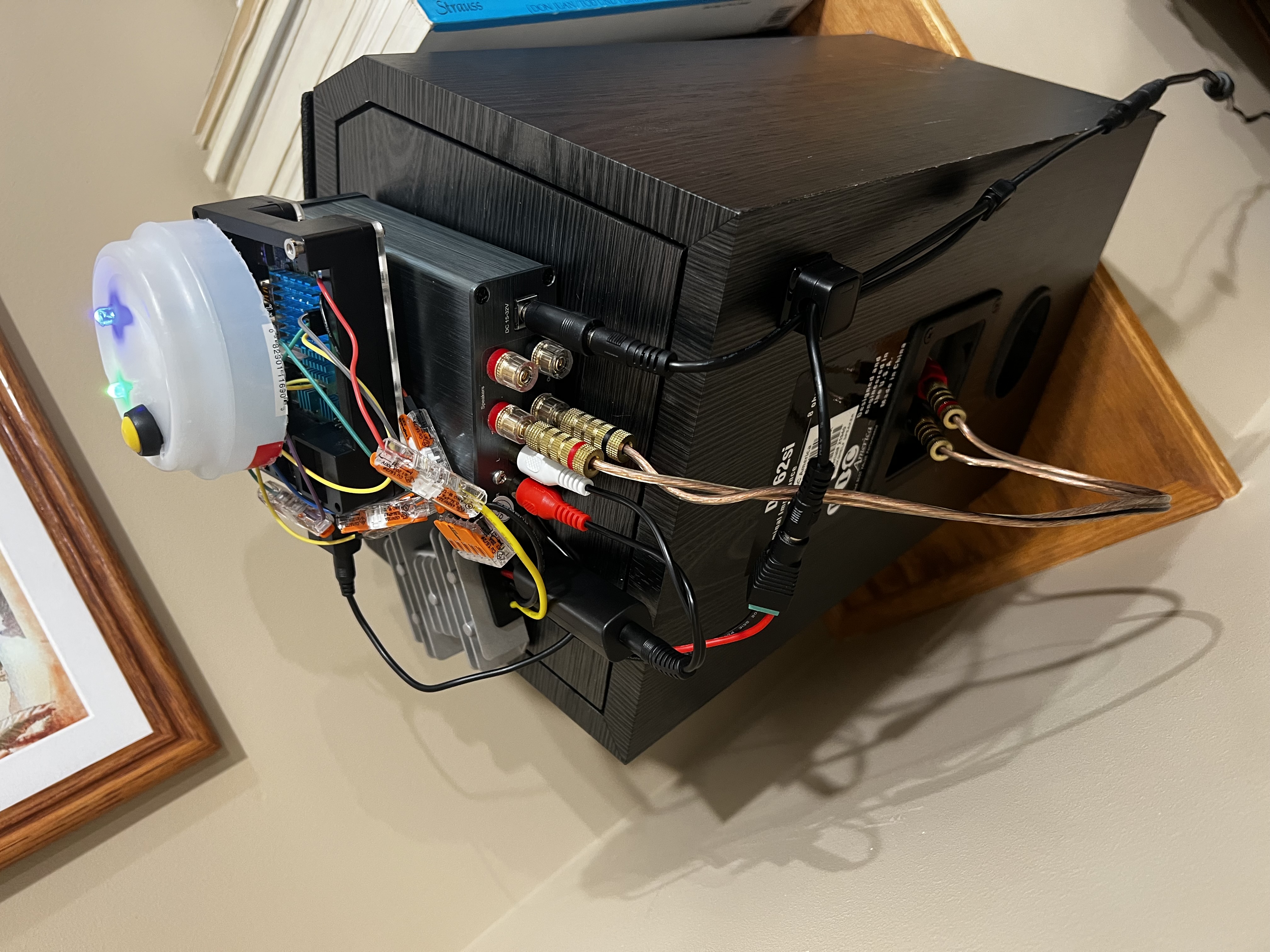
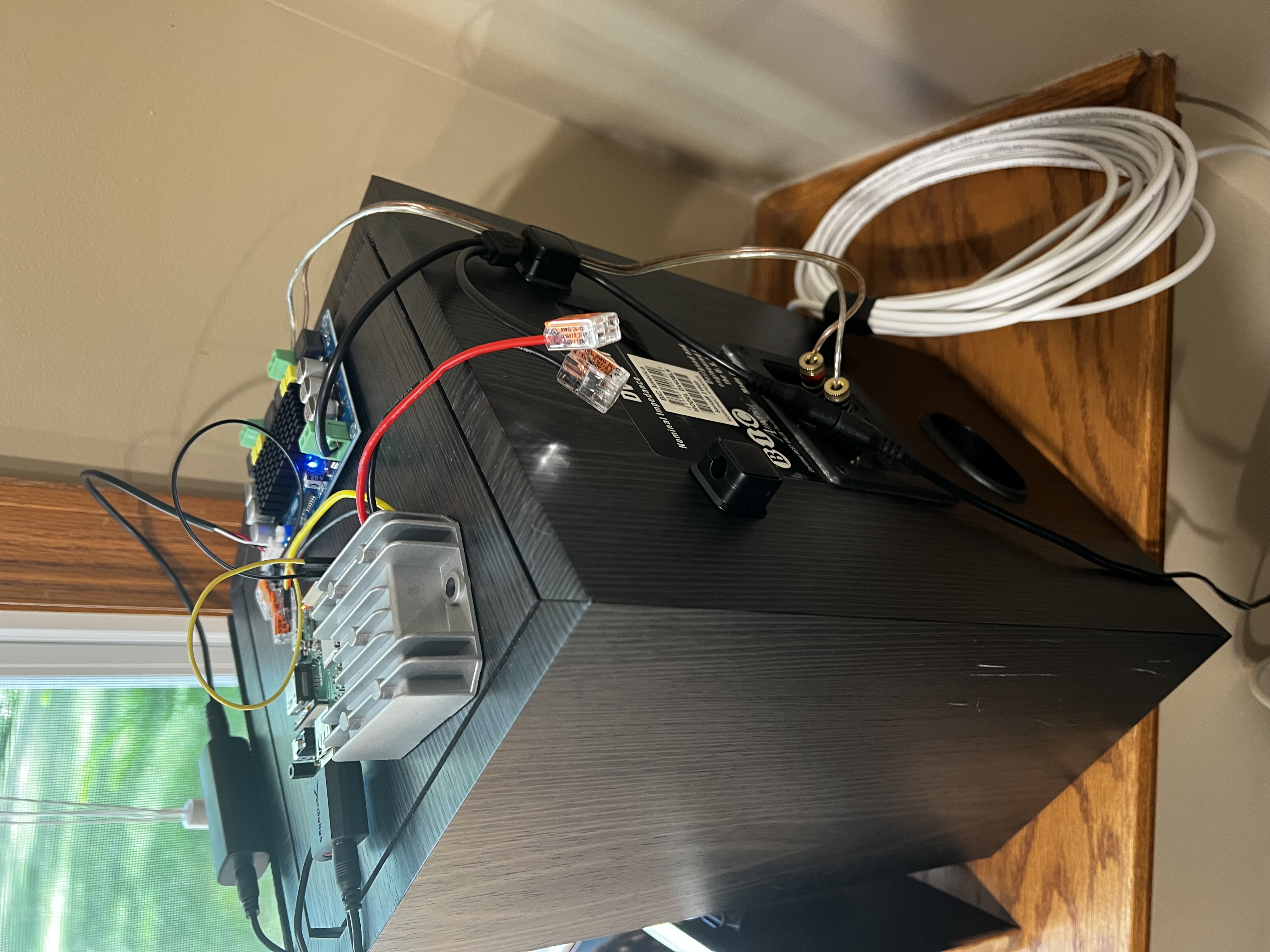
Power
Each speaker runs off one wall outlet. The power supply feeds the amplifier directly and also feeds the buck converter, which steps voltage down to 5V for the Pi. The Pi is powered via its GPIO header rather than the USB port, which bypasses the onboard polyfuse — I measured the buck converter output with a multimeter before connecting it, and held my breath when I plugged it in for the first time.
The left speaker’s 24V/4.5A supply came with the Fosi amp. For the right speaker, I went through a box of old power supplies and found a 12V/3A adapter from a decommissioned Linksys router. It fit the barrel connector, the voltage is within the TPA3116D2’s operating range, and it works.
One wiring mistake that cost me an hour: I used 28 AWG stranded wire for the buck converter to GPIO header run. 28 AWG looks fine sitting at idle, but it has enough resistance that under load — specifically, the moment a Bluetooth client connected and the Pi’s CPU and WiFi radio spun up together — the voltage sagged below the Pi’s minimum and it rebooted. This happened reliably enough to be confusing, because the Pi came back up cleanly every time and nothing in the logs pointed to power. The fix was replacing the run with heavier gauge wire, after which the reboots stopped entirely. The clue was an undervoltage warning in the kernel log — dmesg showed the lightning bolt symbol event right before each reboot, which pointed directly at the power rail rather than software. For any GPIO power feed, use at least 22 AWG.
Audio Stack
The left Pi receives Bluetooth A2DP audio from a phone via BlueZ and PipeWire. A bridge script monitors the PipeWire session for a Bluetooth source, then pipes the audio stream into a named FIFO file on disk. Snapcast server reads from the FIFO and broadcasts a precisely timestamped stream over WiFi. The right Pi runs a Snapcast client that connects to the left speaker and plays back the stream through its USB audio adapter. Both speakers stay within about one millisecond of each other.
After getting audio working, both speakers had an audible hum — a classic ground loop, caused by the USB audio adapter and the amplifier sharing a ground path through the power rail. The fix was a pair of ground loop noise isolators (2 Packs Ground Loop Noise Isolator for Car Audio/Home Stereo System) — 3.5mm inline adapters that sit between the USB adapter’s headphone output and the amp input on each speaker. The hum disappeared immediately.
The trickiest part was the bridge script. When a phone disconnects, the PipeWire Bluetooth source disappears, which kills the audio pipe. Rather than watching for D-Bus events to restart it, the script just polls every two seconds and relaunches pacat when a source reappears. Unglamorous, but reliable.
Another non-obvious issue: pactl has to run as the same user who owns the PipeWire session. Running the bridge service as root causes it to silently connect to an empty PipeWire instance. The systemd unit sets User= and XDG_RUNTIME_DIR explicitly to match the logged-in user.
Pairing Button and LEDs
Without a screen or keyboard, there needed to be some way to put the left speaker into Bluetooth pairing mode. A push button wired to GPIO 22 handles that. Press it, and the speaker becomes discoverable for 60 seconds. A Python daemon (running as a systemd service) handles the button input via gpiozero and monitors BlueZ connection events over D-Bus to keep the LED states accurate. The green LED comes on when the Pi boots. The blue LED blinks during pairing and goes solid when a device is connected.
The only gotcha here was threading: the GLib main loop (needed for D-Bus events) and the gpiozero button callback both need to run concurrently. Moving the 60-second pairing timeout into a background thread kept the main loop unblocked.
Right Speaker
The right speaker has no button and no LEDs — it connects to the left speaker automatically on boot via mDNS and starts playing as soon as audio is available. Both speakers come up on their own after a power cycle. The whole system is controlled from one place: the left speaker, either by pressing its button or opening the web interface.
One wiring step that took longer than expected: connecting the USB audio adapter to the TPA3116D2’s JST audio input. The JST connector has three pins — LIN, GND, and RIN — and the 3.5mm plug has tip (left channel), ring (right channel), and sleeve (ground). Since the right speaker plays only the right channel, ring goes to RIN and sleeve goes to GND. The tip is left unconnected. Getting that wrong the first time produced silence, which was a good outcome compared to the alternatives.
Web Interface
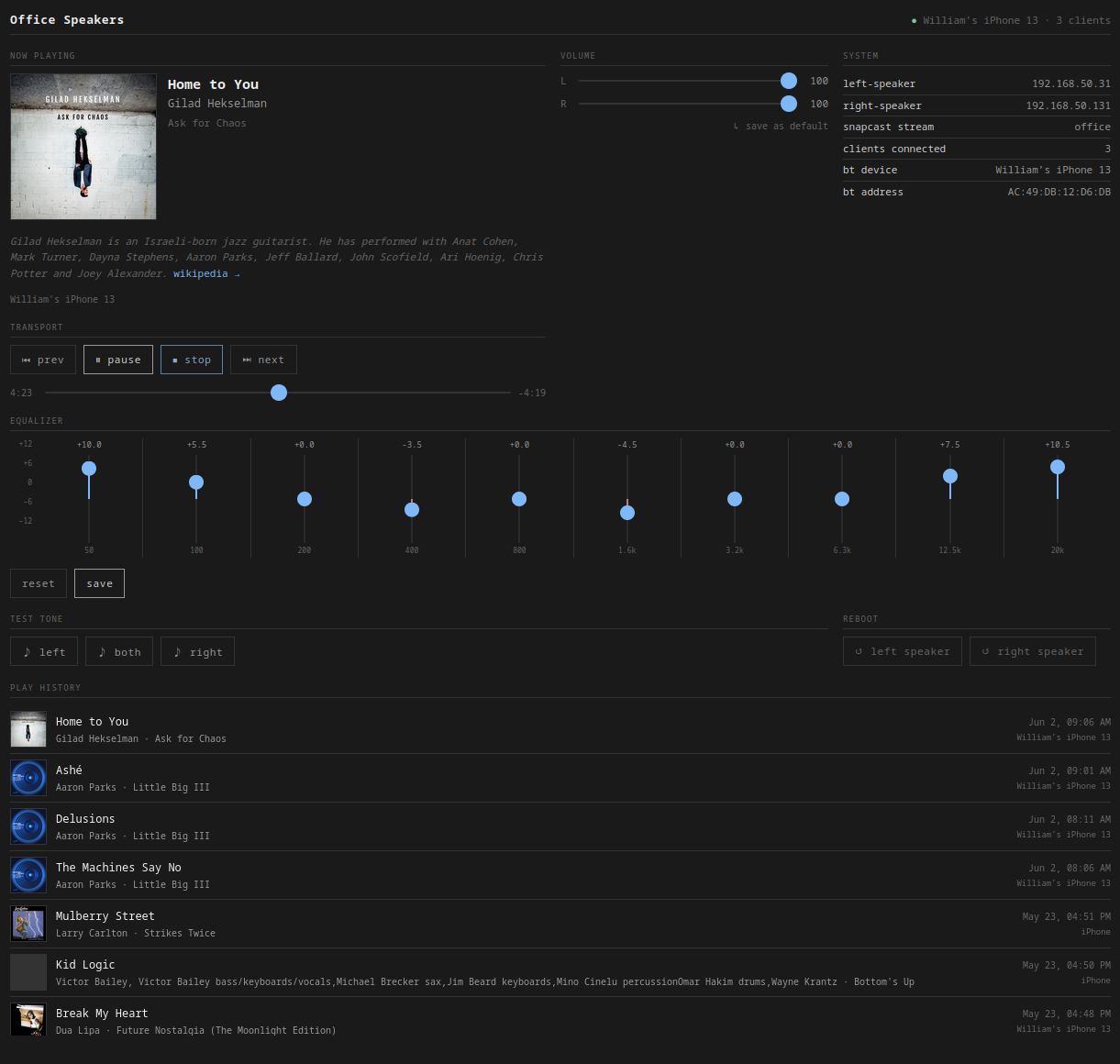
Once the speakers were working, I added a web interface — a FastAPI app running on the left Pi at http://left-speaker.local:8080. It shows the currently playing track with album art (via BlueZ MPRIS), lets me adjust each speaker’s volume independently (via Snapcast JSON-RPC), and includes a 10-band graphic EQ (ffmpeg filter chain applied to the audio bridge, with about one second of silence when settings change). There are transport controls, a test tone generator for verifying each speaker independently, and reboot buttons for both Pis.
Conclusion
This was a genuinely fun build. The thing I was most apprehensive about — the wiring — turned out to be the most satisfying part, mostly because I used WAGO lever-nut connectors throughout instead of soldering. I did almost no soldering on this project: just the two LEDs and the pairing button. Everything else snaps into a WAGO and can be pulled apart and reconfigured without any heat. I’ll be using them in every future hardware project.
The AI-assisted workflow held up well. Claude helped design the architecture, wrote the setup scripts, and caught wiring issues before they became problems. My job was to sit at the bench, execute, and debug what didn’t work — which turned out to be a good division of labor.
Next up: adding a subwoofer.